-
- Open http://dl.altera.com/?edition=lite
- Login and click on desired Quartus version download
- Click in the individual file links to start download (Akamai DLM3 Download Manager might not work).
- Extract Quartus installer.
- Run setup.sh: ./setup.sh
- Select desired devices.
- For launching modelsim, install libxft2 32 bit version library: sudo apt install libxft2:i386. Then execute
./vsimin the path intelFPGA_lite/17.1/modelsim_ase/linuxaloem/
Año: 2018
#define round(x) x >= 0.0 ? (int)(x + 0.5) : ((x - (double)(int)x) >= -0.5 ? (int)x : (int)(x - 0.5))Example:
#include <stdio.h>

#define round(x) x >= 0.0 ? (int)(x + 0.5) : ((x - (double)(int)x) >= -0.5 ? (int)x : (int)(x - 0.5))

void main(void){
   float f1 = 3.14, f2 = 6.5, f3 = 7.99;
   int r1, r2, r3;
   r1 = round(f1);
   r2 = round(f2);
   r3 = round(f3);


   printf("r1 = %d\nr2 = %d\nr3 = %d\n", r1, r2, r3);
}
The console output is:
r1 = 3
r2 = 7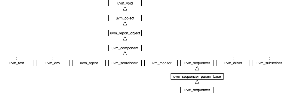
r3 = 8UVM introduces the concept of phases to ensure that all objects are properly configured and connected before starting the runtime simulation. Phases contribute to a better synchronised simulation and enable to the verification engineer to get better modularity of the testbench.
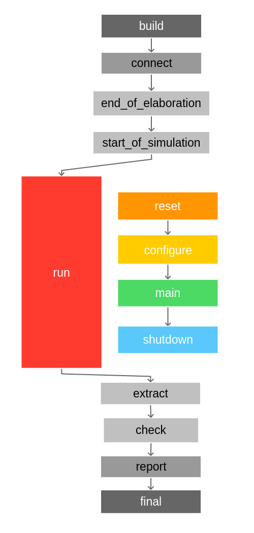
UVM phases consists of:
- build
- connect
- end_of_elaboration
- start_of_simulation
- run
- reset
- configure
- main
- shutdown
- extract
- check
- report
- final
The run phase has been simplified to get a better picture of how phases worked. Nevertheless, all subphases in the run phase have a pre_ and post_ phase to add flexibility. Therefore, the run phase is actually composed by the following phases:
- run
- pre_reset
- reset
- post_reset
- pre_configure
- configure
- post_configure
- pre_main
- main
- post_main
- pre_shutdown
- shutdown
- post_shutdown
Although all phases play an important role, the most relevant phases are:
- build_phase: objects are created
- connect_phase: interconnection between objects are hooked
- run_phase: the test starts. The run_phase is the only phase which is a task instead of a function, and therefore is the only one that can consume time in the simulation.
UVM phases are executed from a hierarchical point of view from top to down fashion. This means that the first object that executes a phase is the top object, usually
testbench → test → environment → agent → {monitor, driver, sequencer, etc}
Nevertheless, in the connect phase, this happens the other way round in a down to top fashion.
{monitor, driver, sequencer} → agent → environment → test → testbench
To use UVM in your Verilog test bench, you need to compile the UVM package top. To do so, you need to include it on your file by using:
`include "uvm_macros.svh"
import uvm_pkg::*;
The uvm_pkg is contained in the uvm_pkg.sv that must be passed to the compiler. Therefore, it is necessary to indicate the UVM path to the compiler. In Cadence Incisive Enterprise Simulator (IES) is as easy as to specify -uvm switch.
In Modelsim, from Modelsim console, run:
vsim -work work +incdir+/path/to/uvm-1.1d/src +define+UVM_CMDLINE_NO_DPI +define+UVM_REGEX_NO_DPI +define+UVM_NO_DPIAfter compilation, click on Simulate > Start simulation and select the tb in the work library. Then, run the simulation for the desired time.
When an operation such as an addtion or a substraction is done using different size operands than final variable, it is necessary to extend sign to ensure the operation is done properly.
Example:
logic signed [21:0] acc;
logic signed [5:0] data_in;
logic [3:0] offset;
Wrong:
acc = data_in + offset;Sign on data_in will not be respected. data_in will be filled with 0 before doing the operation and won’t be taken as negative (if applies).
Correct:
acc = {{16{data_in[5]}},data_in} + offset;Extend sign to match number of acc_add bits before doing operation