Basic operation
The left hand side of the keyboard uses a Microchip MCP23018 IC, which is an I/O expander with open drain outputs and it can be configured through I2C or SPI. In this case we are going to focus on the I2C protocol only since it is the one used by the main MCU. The MCU is a Teensy 2.0 and it is placed on the right hand side of the Ergodox. It is used for monitoring all the switch status, converting the pressed switches into its corresponding character and sending it through USB to interact with the computer as a usual keyboard.
The MCP23018 has two different GPIO ports, GPIOA and GPIOB, each with 8 I/O pads. In the original Ergodox PCB, port A is used to interact with the columns and port B with the rows.
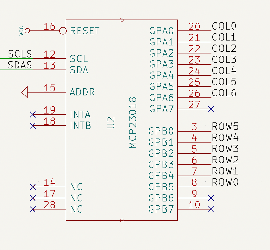 GPIO pads on port B (rows) are configured as inputs and the internal pull-up resistor is enabled on every port B pad. Regarding GPIO pads on port A, they are configured as outputs. According to the datasheet, output pads on the MCP23018 are open-drain, which basically means that the pad value can be internally driven to ground or left floating (high impedance). Since the rows and columns are connected through the mechanical switch and the diode, GPIO’s on port B can determine if the switch is closed (pressed) or open (released) depending on the voltage found at it. A diagram of this scheme is shown below.
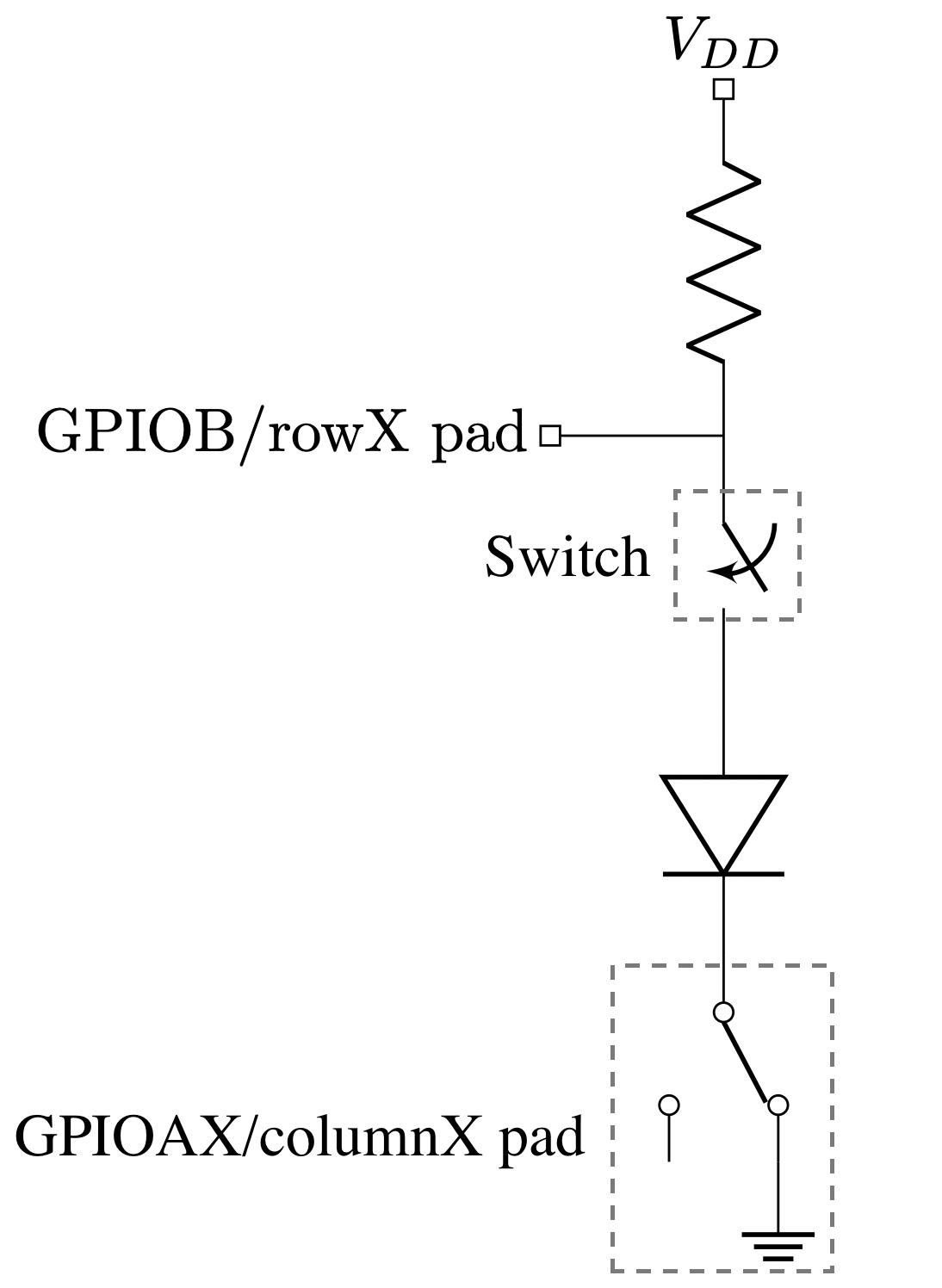
The way the Ergodox firmware determines the state of every switch (closed/pressed or open/released) is by sequentially setting one column to ground while leaving the rest floating. Then, the state of the rows is read. Depending on the state of the switch, the GPIOB reading will be:
- If the switch is released, the voltage at GPIOB will be VDD due to its pull-up resistor. The pad value will be read as 1.
- If the switch is closed, the voltage at GPIOB will be set to 0.0 V. The pad value will be read as 0.
Since the rest of columns are left floating, they won’t interfere on the reading. Once the state of a particular row is read, its value is stored and the operation is repeated until all the available rows are covered. The process of reading the state of all the switches is called a “scan”.
Debugging MCP23018 with Arduino
When I assembled my Ergodox, I loaded the QMK firmware expecting the keyboard to just work. However, there seems to be a hardware issue since the comunication between the LHS and the RHS is not successful. Therefore, I decided to replicated the QMK firmware on an Arduino to have a better understanding on how the MCP and the Teensy interact together and also figure out if there’s really any hardware issue on the PCB’s.
QMK firmware is highly customizable and therefore it can be a little bit intricate when trying to read its code. I tried to distil the most basic functionality regarding the writing and reading done from the Teensy to the Mcp23018 through I2C.
The code below will perform a scan every 1 second and will print through the Serial interface the keyboard matrix result.
mcp23018_debug.c
| |
Output:
| |
where 1 means the switch is pressed and 0 released.
Auxiliary files
i2c_wrapper.h
| |
mcp23018.h
| |
utils.h
| |