Motivation
Several months ago I started trying to find how charge distribution across different capacitors works and I came up to this thought experiment. I used CircuitLab to simulate it and confirm what my intuition said it would ocurr. However, this intuition was wrong and led me to post this question in Electronical Engineering of Stack Exchange in order to find an explanation. Several people took some time to answer the question (really appreaciated), however the answers were not actually satisfactory since they were not really explaining analytically what was behind it. Arout seven months later, I finally found the solution thanks to this video.
For a basic explanation on how to deal with capacitors and charge, please refer to this previous post, written the very same day I started struggling trying to find a solution to this.
Explanation
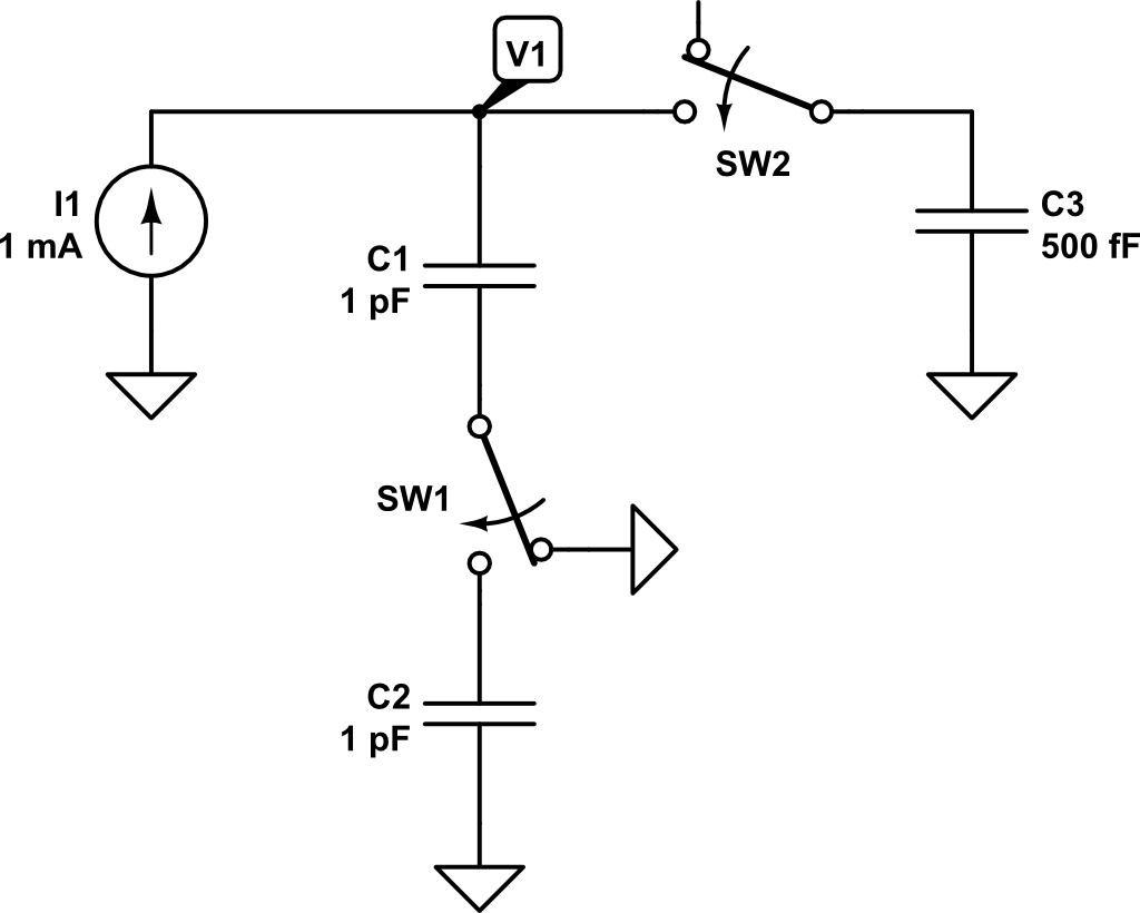
In this circuit, there is an independent DC current source of \(1~mA\) and switches SW1 and SW2 are closed at time \(t=t_1 = 1ns\). From time \(0 < t < t_1\), only \(C_1\) is connected to the current source, so the expected voltage \(V_1\) could be expressed as:
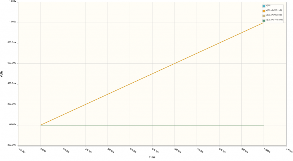
\[V_1 \left( t \right) = \int{\frac{i_1}{C_1}dt} = \frac{i_1 \cdot t}{C_1}\]
The rest of capacitors are discharged and therefore its voltage is \(0~V\) as shown in the following plot:
 Now, at time \(t = t_1 = 1 ns\), switches SW1 and SW2 are closed and capacitors \(C_2\) and \(C_3\) are connected to the circuit. At this point, the current source will keep injecting charge into the capacitors. However, we need first to compute how charge is distributed across capacitors \(C_1\), \(C_2\), \(C_3\). The total charge of the circuit at time \(t = t^-_1\) is:
\[Q_T\left(t^-_1\right) = Q_1 = C_1 \cdot V_1\left(t_1\right)\]
\[V_1\left(t_1\right) = \frac{i_1 \cdot t_1}{C_1} = \frac{1~mA\cdot 1ns}{1~pF} = 1~V\]
By applying superposition theorem, we can determine the contribution of the \(C_1\) voltage on the rest of capacitors. To do so, let’s analyze the following equivalent circuit:
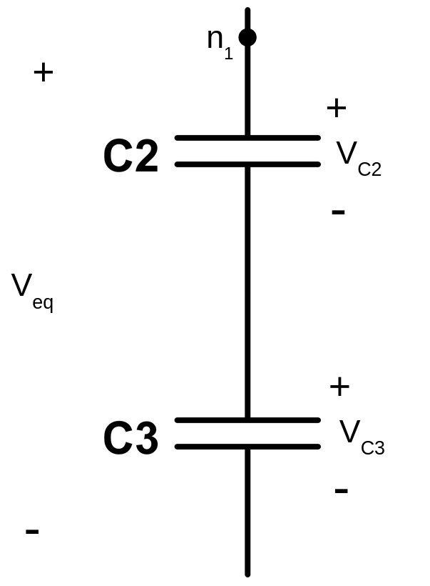
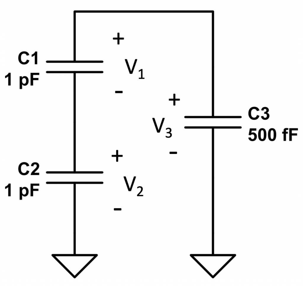 Capacitors \(C_2\) and \(C_3\) are actually connected in series since they share the ground node. So, the circuit could be arranged in the following manner:

The equivalent capacitance would be:
\[ C_{eq} = \frac{C_2 \cdot C_3}{C_2 + C_3} \]
Now, let’s compute the total charge of the system. To do so, let’s rearrange again the circuit. In order to be able to compare the total charge at \(t = t^+_1\) with the total charge \(Q_T\left(t^-_1\right)\), we need to keep being compliant with sign declaration. So \(Q_T\) must be computed from the following point:
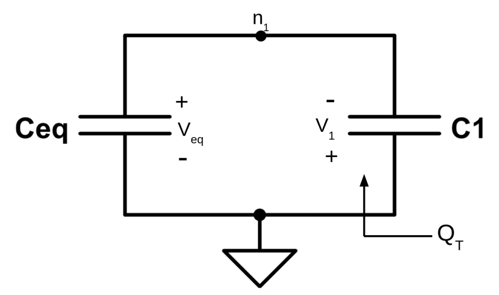 Then, the total charge of the system \(Q_T\left(t^+_1\right)\) would be:
\[Q_T\left(t^+_1\right)= Q_1 – Q_{eq} = V_1\left(t^+_1\right) \cdot C_1 – V_{eq}\left(t^+_1\right) \cdot C_{eq}\]
Due to the way the capacitors are connected, we can assert that \(V_{eq} = -V_1\). Therefore, the total charge of the system can be expressed as a function of \(V_1\):
\[Q_T\left(t^+_1\right)= V_1\left(t^+_1\right) \cdot C_1 – V_{eq}\left(t^+_1\right) \cdot C_{eq} = V_{1}\left(t^+_1\right) \cdot C_{1} + V_1\left(t^+_1\right) \cdot C_{eq}\]
Since the charge in the system must keep constant after the switches position changed, it can be said that:
\[ Q_T\left(t^-_1\right) = Q_T\left(t^+_1\right)\]
This can be expanded to:
\[ C_1 \cdot V_1\left(t^-_1\right) = V_{1}\left(t^+_1\right) \cdot C_{1} + V_1\left(t^+_1\right) \cdot C_{eq}\]
Solving for the new \(V_1\) at time \(t = t^+_1\):
\[ V_1\left(t^+_1\right) = \frac{C_1}{C_1 + C_{eq}} V_1\left(t^-_1\right) \]
Using the values of our example, i.e. \(C_1 = 1~pF\) and \(C_{eq} = \frac{1~pF\cdot0.5~pF}{1~pF+0.5~pF} = 0.333~pF\):
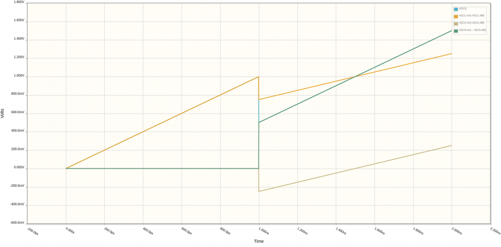
\[ V_1\left(t^+_1\right) = \frac{1~pF}{1~pF + 0.333~pF} \cdot 1~V = 0.75~V \]
\[ V_{eq}\left(t^+_1\right) = -0.75~V \]
Now, we just need to compute the voltages at capacitors \(C_2\) and \(C_3\).
Since voltage \(V_{eq}\) across them is known, we can compute the voltages \(V_{C3}\) and \(V_{C2}\) by solving the capacitive divider they constitute:
\[V_{C3} = \frac{C_2}{C_2 + C_3} V_{eq}\]
\[V_{C2} = \frac{C_3}{C_2+C_3}V_{eq}\]
Replacing the previous expressions with our example values, we get the following voltages:
\[V_{C3} = \frac{1~pF}{1~pF + 0.5~pF}\cdot\left(-0.75\right) = -0.5~V \]
\[V_{C2} = \frac{0.5~pF}{1~pF + 0.5~pF}\cdot\left(-0.75\right) = -0.25~V\]
Finally, we can conclude that:
\[ V_{2} = V_{C2} = -0.25~V\]
\[ V_{3} = -V_{C3} = 0.5~V\]
Theses results are confirmed in simulation:
