A capacitor is an electronic device able to store electrical energy in an electrical field. Usually, the capacitor is defined in its most simple version as a device with two plates with area \(A\), separated by air (or any other dielectric material) a distance \(d\).

By inductiveload – own drawing, done in Inkscape 0.44, Public Domain, Link
If a current source is forced through the capacitor, the electrons (charge) will be deposited in one of the plates, creating in turn a electrical field across them. There won’t be any effective charge transference from one plate to the other because the space between them is filled with a dielectric material (non conductive). However, the electrical field across it can force the repulsion or attraction of charge at the other side of the plate.

By Papa November – self-made SVG version of Image:Dielectric.png, incorporating Image:Capacitor schematic.svg as its base., CC BY-SA 3.0, Link
A capacitor is characterized by its capacitance. The capacitance is measured in Farads (F) and defines the ratio between the amount of charge needed to increase one volt at the terminals of the capacitor.
\[ C= \frac{Q}{V} \]
Therefore, a capacitor with 1 F will need 1 Coulomb (1 C) of charge to set 1 V across its terminals. Remember, that 1 C represents the amount of energy transported by a constant current of 1 A in 1 second.
Behavior of a capacitor connected to a DC current source
Let’s see what happens when we connect a DC current source to a capacitor. Transforming a little bit the previous expression, we can obtain:
\[ C = \frac{Q}{V} \Rightarrow V = \frac{Q}{C} \]
As \(Q = \int{i\left(t\right) dt}\), we can get the voltage across the capacitor as a function of the time and the current:
\[ V\left(t\right) = \frac{1}{C} \int{i\left(t\right) dt} \]
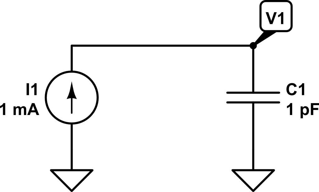
Therefore, if we inject a constant current of \(1~mA\) for \(1~ns\), the voltage \(V_1\left(t\right)\) will be as follows:
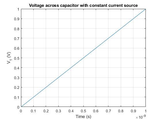
In this example, what would be the charge stored in the capacitor at time \(t_1 = 1~ns\)?
\[ C = Q/V \Rightarrow Q = C \cdot V = 1~pF · 1V = 1\cdot10^{-12}~C \]
Now, what would be the value of the voltage \(V_1\) if at time \(t_1 = 1~ns\) a second capacitor \(C_2\) (discharged) of \(2~pF\) of capacitance is connected?
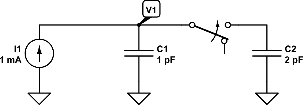 At that very moment in which the second capacitor is connected in parallel, the charge in \(C_1\) will be distributed between \(C_1\) and \(C_2\).
The effective capacitance now is \(3~pF\) (\(1~pF + 2~pF\)). Remember that using the capacitance definition, we got:
\[ V = \frac{Q}{C_p} = \frac{Q}{C_1 + C_2} = \frac{1\cdot 10^{-12} C}{1\cdot10^{-12}~F + 2\cdot10^{-12}~F} = 0.333~V \]
Therefore, as the capacitance now has increased and the charge remains the same (although shared between \(C_1\) and \(C_2\)), according to the previous expression the voltage has to drop.
 If we would like to know the charge stored in every individual capacitor at time \(t_1 = 1~ns\), we could compute it as:
\[ Q = C \cdot V\]
\[ Q_1\left(t_1 = 1~ns\right) = C_1 \cdot V_1\left(t_1 = 1~ns\right) = 1~pF \cdot 0.333~V = 3.33\cdot10^{-13}~C\]
\[ Q_2\left(t_1 = 1~ns\right) = C_2 \cdot V_1\left(t_1 = 1~ns\right) = 2~pF \cdot 0.333~V = 6.66\cdot10^{-13}~C\]
The result is consistent with the previous calculation stating that the amount of charge at \(t_1=1~ns\) was \(Q = 10^{-12}~C\).
Finally, let’s see what happens if at time \(t_2 = 2~ns\) the capacitor \(C_2\) is again disconnected and only capacitor \(C_1\) is connected to the current source.
At time \(t_2 = 2~ns\) the voltage \(V_1\) will have increased to:
\[V\left(t_2 = 2~ns\right) = V_1\left(t_{1}^{+}\right) + \frac{1}{C_1 + C_2} \int_{t_1 = 1~ns}^{t_2 = 2~ns}{i\left(t\right) dt} \]
\[V\left(t_2 = 2~ns\right) = 0.333 V + \frac{1}{1~pF + 2~pF} \int_{t_1 = 1~ns}^{t_2 = 2~ns}{1~mA~dt} = 0.333~V +0.333~V = 0.666~V\]
Now the charge will be distributed as follows:
\[ Q_1\left(t_2 = 2~ns\right) = C_1 \cdot V_1\left(t_1 = 2~ns\right) = 1~pF \cdot 0.666~V = 6.66\cdot10^{-13}~C\]
\[ Q_2\left(t_2 = 2~ns\right) = C_2 \cdot V_1\left(t_1 = 2~ns\right) = 2~pF \cdot 0.666~V = 1.22\cdot10^{-12}~C\]
If \(C_2\) is disconnected, the charge stored in it will be lost and won’t be redistributed towards \(C_1\). Therefore, the total amount of charge in the system at \(t_2 = 2~ns\) will only be that on \(C_1\).
Now, the voltage increment at the same rate as in the period \(0 < t < t_1 = 1~ns\).
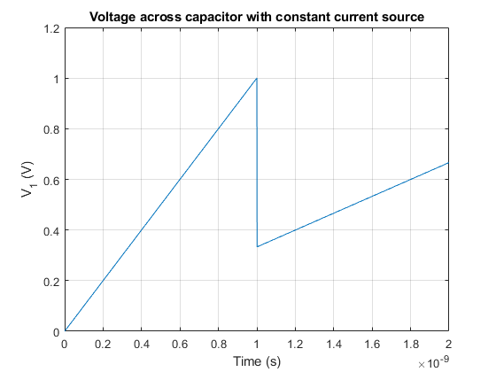
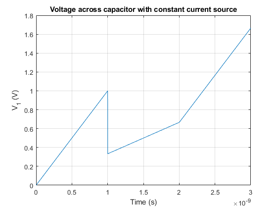
Therefore, if we plot the voltage from \(t=0~ns\) to \(t_3 = 3~ns\), we would get the following voltage profile for \(V_1\):
Un comentario en «Current source and switched capacitors in parallel»