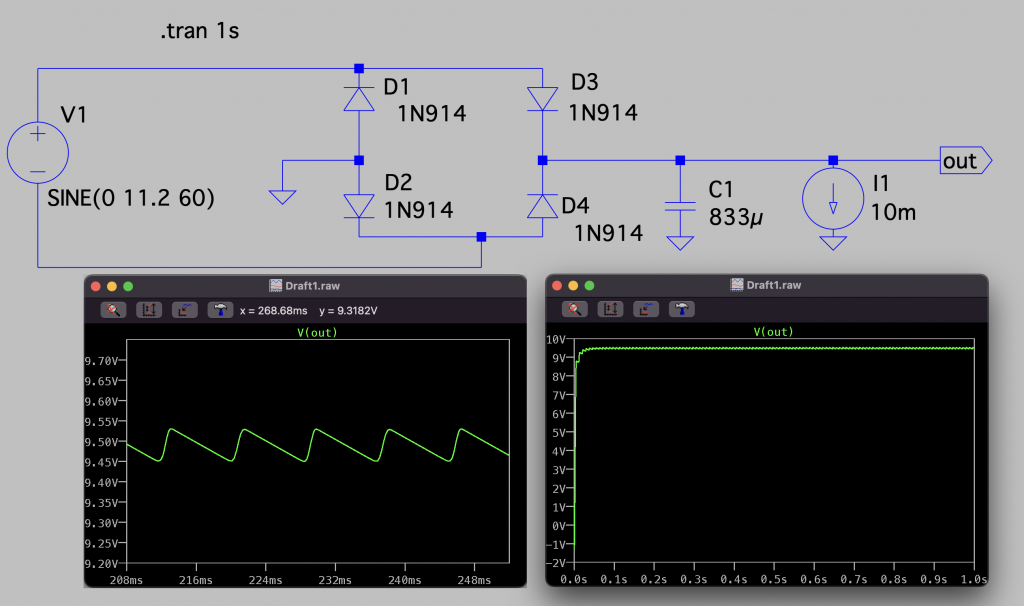
Design a full-wave bridge rectifier circuit to deliver 10 V dc with less than 0.1 V (pp) ripple into a load drawing up to 10 mA. Choose the appropriate ac input voltage, assuming 0.6 V diode drops. Be sure to use the correct ripple frequency in your calculation.
The relationship between current and voltage in a capacitor is:
\[ Q = C \cdot V \]\[ \int{I dt} = C \cdot V \]\[ I dt = C \cdot dV \Rightarrow I = C \frac{dV}{dt} \]\[ dV = \frac{I}{C} dt \]\[ \Delta V = \frac{I}{C} \Delta t~~~\left(1\right) \]
Frequency of the ac signal: \(f\)
\(\Delta t = \frac{1}{2f}\)
If we need \(\delta V = 0.1~Vpp\) by drawing 10 mA, then, from Equation 1:
\[ \Delta V = \frac{I}{C} \Delta t \]\[ C = \frac{I}{\Delta V} \Delta t\]\[ C = \frac{10^{-2}}{0.1~V}\cdot \frac{1}{2f}\]
Let’s assume \(f = 60 Hz\), then:
\[C = \frac{10^{-2}~A}{0.1~V}\cdot \frac{1}{2\cdot 60~Hz} = 833~\mu F\]
The capacitor is going to be charged to the input amplitude – the diode voltage drop. Therefore, the amplitude of the ac input voltage should be:
\[ V_{out~max~pp} = V_{in~pp} – 2 \cdot V_{diode~drop}\]\[
V_{in~pp} = V_{out~max~pp} + 2 \cdot V_{diode~drop} = 10~V + 2\cdot 0.6~V = 11.2~V
\]
If simulated on a SPICE simulator, the results are confirmed. The difference on the final rectified voltage comes from the dynamic behaviour of the model used for the diodes, which is not an ideal model with 0.6 V threshold as assumed in the exercise’s data. The approximation of 0.6 V drop is more or less decent since the final voltage is around 9.5 V.
Therefore, the key aspects to remember from this circuit are:
- The output voltage only depends on the input voltage
- The ripple depends both in the output current and the capacitance value. The more current, the more charge is extracted from the capacitor. Therefore, voltage discharge increases. Same rationale works on the capacitance: the greater the capacitance, the more charge can be stored for a given capacitor voltage
